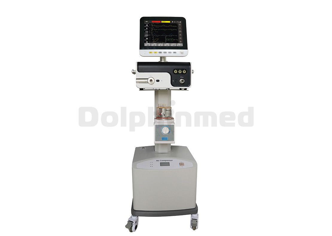
What is The Basic Structure of the Ventilator?
The basic structure of the Display ICU Ventilator mixed with electronic circuits and mechanical pneumatic circuits is generally composed of an oxygen source, a solenoid valve, a mixed air device, a pressure limiting valve, a humidifier, and a temperature control circuit, an airway resistance meter, a breathing valve, and a signal. The box and the solenoid valve control circuit are composed of nine parts.
(1). "Oxygen source"
It is a device for storing oxygen and is designed to provide the patient with the oxygen needed for inhalation. Ventilator manufacturers are typically supplied by a high-pressure oxygen cylinder or compressed air.
(2). Solenoid valve
The solenoid valve is an "oxygen source" switching valve. It differs from the mechanical regulating valve in electrical control, that is, by controlling the opening and closing of the solenoid coil current to control the opening and closing of the valve, so that the airflow is turned on or off. It works somewhat like a normal relay.
(3). Mixed air
The air mixing device utilizes the principle of reducing the lateral pressure of the high-speed fluid, and the oxygen is injected from the high-speed nozzle to generate a negative pressure zone. The air pressure on both sides is greater than the negative pressure zone, and the air is trapped in the high-speed flowing oxygen.

(4). Pressure limiting valve
The pressure limiting valve is a gas pressure limiting device that ensures that the gas is output at a certain pressure. When the machine is shipped from the factory, the Hospital Ventilator Machine Manufacturer is generally adjusted to 6kPa (60cmH2O). If the machine output air pressure exceeds this value, the gas will be automatically vented to ensure patient safety.
(5). Humidifier and temperature control circuit
It is a thermostat with constant temperature water that allows gas to enter and exit. The device can eliminate the stimulation of the cold air of the patient's lungs, avoid dehydration of the respiratory mucosa, and play a role similar to the humidification, filtration, and warmth of the human respiratory tract. The temperature control circuit is a circuit that regulates the temperature of the water in the humidifier and keeps it constant.
(6) Airway resistance table
This table is a device used to indicate the size of the patient's airway resistance. From respiratory resistance and oxygen source pressure, ventilator manufacturers can separately calculate the oxygen content (excluding the oxygen content in the air) and the tidal volume.
(7). Breathing valve
Adult Anesthesia Vaporizer Factory uses a pneumatic method to drive two flaps to achieve an organic combination of exhalation, inhalation, and negative pressure. When inhaling, the inspiratory valve is opened, the machine supplies air to the patient in one direction, and when inhaling, the inspiratory valve is closed, and the exhaled gas is discharged from the expiratory channel.
(8). Signal box
The signal box is constructed by a sensitive elastic diaphragm that drives a pair of sealed electrical contacts. When the suction negative pressure reaches a certain value, the contact is broken and the signal box outputs a pulse signal. In this way, the patient's inspiratory negative pressure is converted into an electrical signal, and input to the "solenoid valve control circuit" to achieve the control of the solenoid valve.
(9). Solenoid valve control circuit
It is a logic control system consisting of pulsed digital circuits that control the on or off of the solenoid valve. Finally, Display ICU Ventilator manufacturers achieve the required respiratory rate, machine-controlled breathing, synchronized breathing, and automatic conversion of active and passive breathing through the pneumatic path.


 English
  French
  Chinese
  Spanish


